Welcome To The Regenerative Waterscaping Series
Regenerative waterscaping is the art and science of shaping and tending landscapes to maximize the productive, ecological and aesthetic benefits of water as it moves through them. The 4 R’s Of Regenerative Hydrology details the paradigm that guides successful design and implementation of the many different types and variants of water patterning elements detailed in the remaining posts, and is a recommended introduction for the entire series. When applied in alignment with your holistic context (people, place and purpose), these elements will knit together to create the foundation for true abundance – a landscape that works with Nature.

Erosion Prevention And Repair Elements
Introduction
Soil erosion is a serious problem in most contexts. Stopping active soil erosion is a prerequisite for rebuilding soil, and the elements detailed here are tools to help us do just that in a wide variety of landscapes. However, no treatment is a panacea, and each must be evaluated based on the unique parameters of the situation in which it is to be applied. Improperly designed or applied erosion control measures are a waste of resources at best, and can exacerbate the underlying problem at worst.
Each element write up begins with a description of the element and the functions it performs, followed by a list of context-specific design criteria for determining whether or not it is appropriate in a given situation, general rules of thumb to follow when designing and installing it, and additional resources for continued learning.
Erosion Prevention & Repair Elements Index
*click to jump to a specific element
- Vertical Straw Mulch
- Wattles
- Media Lunas
- Berms
- Brush-Mineral
- Wood Chip
- One-Rock Dams (ORDs)
- Weirs – stone, brush
- Brush Packing
Soil Stabilization
- Contour Vetiver Grass Plantings
Headcut Treatments
Description: Headcuts are sudden drops in the water course (like a miniature cliff), and are the primary way that incised gullies form. They are particularly damaging to landscapes because, once formed, they continue moving up-watershed (kind of like unzipping a zipper, except they move uphill), growing in size and severity, causing ever-worsening erosion and dehydration of the surrounding terrain every time water flows through them. Headcuts are landscape dehydrators because they very quickly disconnect flowing water from its ancestral floodplain via downcutting and incision, ultimately forming a gully. Once the water is in the incision, it cannot effectively hydrate the floodplain several inches or many feet above it. This leads to type conversion of surrounding vegetation towards more upland, drought-hardy plant species, which are often lower quality forages for grazing animals and wildlife.
Bottom line: Avoid initiating headcuts at all costs. If you have them on your property, get them stabilized as soon as possible – otherwise with every passing rainfall event that generates surfaces run-off you will be losing topsoil and drying out the surrounding landscape.

The gallery below contains images of many of the different headcuts we have encountered over the years.

Leading headcut seen from up-watershed. 
Deep headcut incision eroding a pasture bottom. 
Headcut from un-patterned sheetflow run off on access road. 
Same headcut seen from down-watershed. 
Headcut down to bedrock. 
Beginning exacavation of the largest headcut to prepare for zuni bowl construction. 
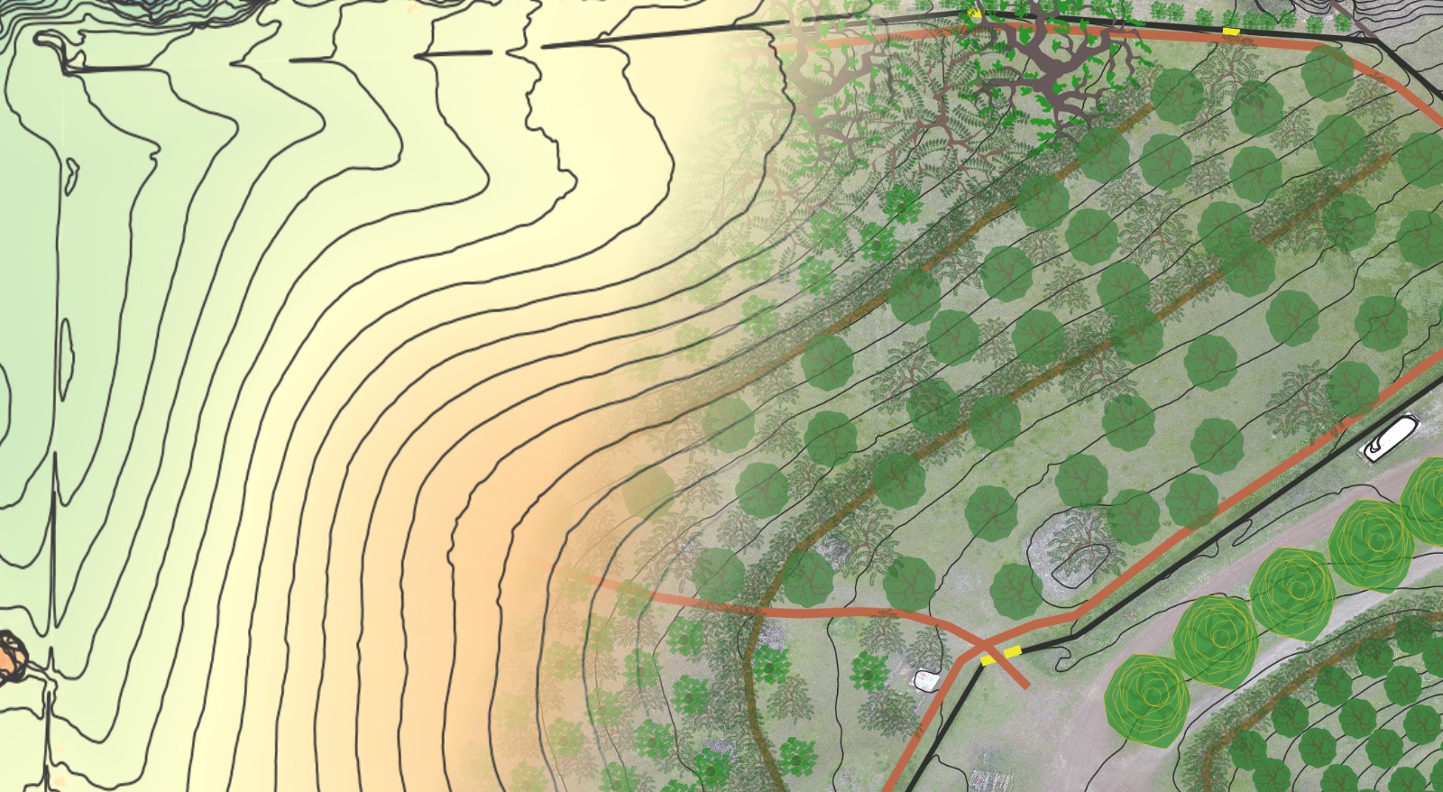
One of the many headcuts eating away an orchard road. 
Headcut incision at the edge of a road. 
A young headcut, started from a cattle rut. 
A large headcut moving up a sandy valley bottom. 
An 8′ deep headcut eating into an orchard road. 
Headcut has reached an orchard road. 
Headcut approaching an orchard road. 
6′ deep headcut in creekline, being temporarily stabilized by a honey locust tree (tope of frame) that has been completely undercut. 
Headcut from orchard road run off. 
Headcut moving up a small creek line, stopped by a tree and the stones its roots held in place.

Zuni Bowls
Description: A zuni bowl is a geologically armored plunge pool constructed from tightly knit stone that halts the up-watershed migration of a headcut.
Function(s): Zuni bowls create an armored lip and basin over which and and into high-energy water flows. The shape of the zuni bowl creates a small plunge pool, containing standing water, into which high-energy, fast-moving water falls. In this way the erosive force of the high-energy water is mitigated and an opportunity for re-patterning the now lower-energy run-off water is created – either within the gully or often times across the surrounding landscape by linking the zuni bowl with swales or infiltration basins.

Zuni bowl with optional 1% drain outlet to swale system. Zuni bowl with swale outlet activated by sandbags blocking the main channel discharge 
Zuni bowl in incised drainage. IMAGE: Ecology Artisans. 
Excavating the outlet of a clogged culvert to install a self-cleaning Energy Dissipation Pool to stop culvert plugging with sediment. 
Remodeled culvert discharge with self-cleaning energy dissipation pool. 
Energy dissipation pool installed at remodeled culvert discharge. 
Large zuni bowl under construction. 
Large armored zuni bowl in incised drainage, fed by armored drain from rolling dip on road above.
Context-Specific Design Criteria for Zuni Bowls
Zuni Bowls are generally a good fit for a specific context when:
- When the grades of the slope are such that excavating a headcut and creating a bowl shape does not require moving much soil (most zuni bowl construction work can be performed by hand).
- Heavy machinery can be used to shape the headcut and lay in rock in certain circumstances (slopes are such that they can be safely operated, and stone required is too large to be safely or efficiently moved by people alone).
- Irregular, angular stone is available on-site or nearby for creating the plunge pool and associated one-rock dam. If limited or no stone is available, see Log-Drop Structures as an alternative headcut-armoring technique.
Zuni bowls may not be a good fit for a specific context when:
- Terrain is too steep to allow for the creation of the armored bowl – i.e. too much soil would have to be moved in order to create a stable structure. As a general rule, if the vertical drop exiting a zuni bowl would be equivalent or greater than the depth of the incision which the bowl is designed to address, the terrain is too steep and the incision is located within the “transport zone” – i.e. an area where the slope is so steep that de-energization of the water flow is not possible (the water would speed up again immediately upon exiting the zuni bowl).
- In these situations, the best option is to utilize armored drains to transit the water through the steep section of terrain in a non-erosive fashion, and de-energize it once the slope begins to flatten out at the key point or a pseudo-key point (see Water Infiltration Earthworks > Keyline Subsoil Ripping to learn more about identifying the key points in your landscape).

General Design & Installation Considerations for Zuni Bowls
- The headcut overhang and sides should be laid back to a 1:1 or 2:1 slope, and all dead or dying vegetation removed from the pour-over lip.
- Measure the height of the headcut drop. Then measure down-watershed 3-4x this length. This will be the approximate extent of the bowl. Begin by digging a small trench at this point and setting in a rock splash apron. The splash apron should be set at the same height as the native gully bottom.
- Underseed the area where the zuni bowl is to be constructed with native grass seed or other appropriate erosion control seed mix.
- Utilizing the largest rocks available, create a tightly knit row of rocks just upstream from and sitting slightly atop the splash apron. These rocks should be approximately 1/2 the total height of the headcut. These rocks will create the exit sill of the zuni bowl.
- Armor the bottom of the zuni bowl with a single layer of tightly knit stone, working from one end to the other to eliminate any gaps between stones.
- Starting from the upstream side of the exit sill, begin building up the sides of the bowl to form the walls. Build up towards the native grade knitting the stone as tightly as possible. Cracks and gaps should be infilled with smaller material, such as road base or smaller gravel, to prevent piping of water through the rocks that could lead to failure of the structure. Try to maximize stone-to-earth contact as you go, building up in courses. Use “gravity glue” to tie the rocks together. Test each course by walking up and down on it – the stones should not slip or wiggle underneath your weight.
- Utilize flat stones for the pour-over lip, set to the same height as the native ground above the headcut lip. Setting the pour over lip higher than the native terrain may lead to the flow path being altered and the water flowing around the zuni bowl or entering it at an unintended location, both of which are to be avoided.
- Whenever the terrain permits it, always construct a one-rock Dam (ORD) immediately downstream of the zuni bowl. Place the upstream edge of the ORD downstream from the zuni bowl splash apron approximately 6-8x the height of the headcut, or far enough so that the anticipated deposition zone of the ORD will reach up to but not past the splash apron of the zuni bowl (see One-Rock Dams to learn how to construct them and their role in supporting the function of zuni bowls in rehabilitating incised drainages).
Resources for Continued Learning about Zuni Bowls
- Rainwater Harvesting For Drylands & Beyond – Brad Lancaster
- Zuni Bowl YouTube playlist
- [PDF] – Ecology Artisans Erosion Control Training Packet – pgs 57-60

Energy Dissipation Pools
Description: Stone lined pools installed at the transition point where a high energy / high velocity flow needs to be pacified before transiting through a lower energy / lower velocity area. EDPs are different from zuni bowls in that they are not installed into active headcuts, rather they are built into drainage paths where concentrated run-off needs to be pacified to prevent the formation of a scour pit and initiation of a headcut in the first place.
Function(s): To de-energize / slow down high energy / high velocity water so that they may be patterned into a lower energy system (such as a swale or infiltration basin) to be infiltrated or slowly moved through the landscape. EDPs are typically installed at the bottom of a “no chance” zone (to borrow a Bil Zeedyk term) – an area where there is no chance to drain run-off water, and typically where both flow velocity and volume increase to a point where they would do damage to native soils if abruptly introduced to them without pacification (i.e. where a steep grade transitions to a much shallower grade suddenly).

Context-Specific Design Criteria for Energy Dissipation Pools
Energy Dissipation Pools are generally a good fit for a specific context when:
- There is a concentrated source of run-off exiting a high-energy / high-velocity transport zone and being discharged onto more fragile soils (typically at keypoints or where steep terrain transitions to flatter terrain over a short distance).
- Any place a concentrated flow of run-off has to be sped up in order to transit a drainage structure to keep it from clogging (such as a rolling dip, culvert, armored drain, or other high volume / high energy drain).
- Anywhere that a concentrated flow of water is falling onto native soil on a slope (this often happens with improper culvert installations in steeply sloped terrain).
- Most often additional flow spreading structures (media lunas, one rock dams, berms etc.) should be installed in concert with an EDP to spread out the water.
Energy Dissipation Pools may not be a good fit for a specific context when:
- When the substrate that the water will be discharged onto is non-erosive (i.e. bedrock, highly porous gravel etc) and EDP is not necessary.
- Terrain is too steep to allow for the creation of the armored bowl – i.e. too much soil would have to be moved in order to create a stable structure. As a general rule, if the grade exiting an EDP is equivalent to the grade of the inbound flow, the terrain is too steep and the incision is located within the “transport zone” – i.e. an area where the slope is so steep that de-energization of the water flow is not possible (the water would speed up again immediately upon exiting the EDP).
- In these situations, the best option is to utilize armored drains to transit the water through the steep section of terrain in a non-erosive fashion, and de-energize it once the slope begins to flatten out at the key point or a pseudo-key point (see Water Infiltration Earthworks > Keyline Subsoil Ripping to learn more about identifying the key points in your landscape).
General Design & Installation Considerations for Energy Dissipation Pools
- Begin by digging a small trench at the point where the bowl will end on the downstream side. Set the splash apron here at the same height as the native gully bottom.
- Underseed the area where the zuni bowl is to be constructed with native grass seed or other appropriate erosion control seed mix.
- Utilizing the largest rocks available, create a tightly knit row of rocks just upstream from and sitting slightly atop the splash apron. These rocks should be approximately 1/2 the total height of the headcut. These rocks will create the exit sill of the energy dissipation pool.
- Armor the bottom of the energy dissipation pool with a single layer of tightly knit stone, working from one end to the other to eliminate any gaps between stones.
- Starting from the upstream side of the exit sill, begin building up the sides of the bowl to form the walls. Build up towards the native grade knitting the stone as tightly as possible. Cracks and gaps should be infilled with smaller material, such as road base or smaller gravel, to prevent piping of water through the rocks that could lead to failure of the structure. Try to maximize stone-to-earth contact as you go, building up in courses. Use “gravity glue” to tie the rocks together. Test each course by walking up and down on it – the stones should not slip or wiggle underneath your weight.
- Utilize flat stones for the pour-over lip, set to the same height as the native ground above the headcut lip. Setting the pour over lip higher than the native terrain may lead to the flow path being altered and the water flowing around the zuni bowl or entering it at an unintended location, both of which are to be avoided.
- Whenever the terrain permits it, always construct a one-rock Dam (ORD) immediately downstream of the Energy Dissipation Pool. Place the upstream edge of the ORD downstream from the EDP splash apron approximately 6-8x the depth of the EDP, or far enough so that the anticipated deposition zone of the ORD will reach up to but not past the splash apron of the EDP (see One-Rock Dams to learn how to construct them and their role in supporting the function of zuni bowls in rehabilitating incised drainages).
Resources for Continued Learning about Energy Dissipation Pools
- Rainwater Harvesting For Drylands & Beyond – Brad Lancaster

Armored Rundowns
Description: An rock ramp constructed of knitted stone used to stabilize small headcuts.
Function(s): To transition high-velocity flows down a steep or sudden grade change without eroding the native soils underneath.

Armored drain connection a rolling dip to an armored drainage with zuni bowl. 
Armored rundown from the drain point in a rolling dip discharging into a small zuni bowl. Armored rundown with a dished center to keep flows in the middle of the armored course. 
Armored step-down – rolling dip depression visible in background taking discharge from the shop roof and transiting it to the swale. 
Armored step-down connecting a rolling dip to the swale above the orchard terraces.
Context-Specific Design Criteria for Armored Rundowns
Armored Rundowns are generally a good fit for a specific context when:
- The distance to be covered is relatively short (generally up to 3x the height of the drop).
Armored Rundowns may not be a good fit for a specific context when:
- The distance to be covered is relatively long (greater than 3x the height of the drop)
General Design & Installation Considerations for Armored Rundowns
- Cut or lay back the edge of the headcut or drop to be transited, ideally to a 3:1 or gentler slope. Trim back the soil until live plant roots are exposed. Seed the area with perennial erosion control grasses or other hairnet root plants. These will grow up through the stone and bind them together, enhancing the effectiveness and lifespan of the structure.
- Make sure the rocks at the pour-over lip are at the same elevation of the headcut so that water flows freely over it.
- Shape the area to be armored and slightly dish out the center of the water course (to prevent water from moving around the structure.
- Knit rocks together tightly to prevent piping. Add small, sharp gravel between stones if necessary to better knit them together.
Resources for Continued Learning about Armored Rundowns

Log and Fabric Drops
Description: Also known as log drop structures, log and fabric drops are a stair stepped series of logs underlain with geotextile fabric, generally utilized on larger in-channel headcuts where the fall is 4′ or greater and/or logs are more easily sourced than stones.
ABOVE IMAGE: National Forest Foundation
Function(s): Stabilizes deep, high-energy headcuts by creating a stable staircase for the water to cascade down without further degrading the leading edge of the headcut. Using logs and cutting them to size allows for large headcuts to be protected easier than using stones that would be so large and heavy as to require a small excavator to move into place.
Context-Specific Design Criteria for Log and Fabric Drops
Log and Fabric Drops are generally a good fit for a specific context when:
- Headcut is deep and high energy.
- Stone is either not availabe on-site, or would be too expensive to haul in or too heavy to work with given the size of the headcut that requires stabilization.
- Logs are available on-site or nearby and can be sourced cost effectively.
Log and Fabric Drops may not be a good fit for a specific context when:
- Stone is available on-site, and is of proper size to handle the anticipated flow volumes.
General Design & Installation Considerations for Log and Fabric Drops
- Detailed instructions available starting on page 41 of Hand-Built Structures for Restoring Degraded Meadows in Sagebrush Rangelands
- Materials Required
- Geotextile Fabric (silt fencing fabric in 3 foot widths works well and is convenient to use).
- Logs: Logs 6 to 10 inches in diameter and varying lengths from 4 to 8 feet long. (For example, bottom
tier, 8 feet long, second tier, 6 feet, third tier, 4 feet.) Logs should be straight, trimmed and green, or
seasoned, but not rotten. Any protruding knots, limbs, or knobs make stacking very difficult and should be
trimmed. - Wire: one roll of smooth fencing wire or barbed wire.
- Fencing staples: 2 inches long, about 2 lbs.
- Sod clumps: 6” X 6” X 3”. Dig locally.


Resources for Continued Learning about Log and Fabric Drops
Sheet Erosion
Sheet flow erosion occurs when soil reaches full saturation and is no longer capable of infiltrating additional water, or when rainfall is so intense that it arrives faster than the soil is capable of infiltrating it. At this point, water begins to run over the soil surface. Along the way, it picks up soil fines – the smallest particles of soil – and transports them down-watershed. As the run-off moves down-watershed it increases in volume and velocity, enabling it to carry larger and more soil particles. Unchecked sheet flow erosion is a major drain on soil nutrients for any landscape.


The best way to counter sheet flow erosion, and in many cases completely prevent it, is with perennial living soil cover – plants! Living vegetation reduces and prevents erosion in several ways:
- Raindrop impedance – rain drops are intercepted by leaves, stems and branches prior to hitting the soil, greatly reducing their energy and the potential for impact erosion.
- Increased roughness – water has to twist and turn around every bit of vegetation it encounters, forcing it to move slower and thus increasing the opportunity for infiltration.
- Increased infiltration rates – living roots create infiltration channels to move water down into the soil quickly.

Flow Patterning Structures
Depending upon the context, it may be necessary to concentrate small channelized flows before transiting a steep section of landscape or an area prone to erosion (a “transport” zone) to direct them down an armored drain or rock rundown, or to spread out channelized flows upon exiting a transport zone to pattern the water over a wider portion of the landscape. The structures detailed here function to either concentrate or spread water flows.

Media Lunas
Description: Media lunas are level structures made of knitted stone shaped like a crescent moon.
Function(s): Media lunas are used to manage sheet flow in one of two ways; sheet flow collectors (tips of the moon facing downhill) are used to aggregate small rills (<6″ deep) or runnels (<1′ deep) to prevent headcut formation at the head of rill, runnel or gully by creating a stable transition from sheet flow to channelized flow, and flow spreaders (tips of the moon are facing uphill) to create a soil deposition area on relatively flat (shallow grade) ground where potentially erosive channelized flow can be transitioned to more passive sheet flow.

Context-Specific Design Criteria for Media Lunas
Media lunas are generally a good fit for a specific context when:
- Concentrated, high-energy flows need to be spread out after being de-energized by a change in grade, an energy dissipation pool, zuni bowl, log and fabric drop, culvert, rolling dip, armored drain etc.
- Stone is available on-site or locally.
Media lunas may not be a good fit for a specific context when:
- Grades are too steep – they should either be installed at the heads of rills or runnels before gully formation, or at or below the keypoint in the landscape where the slop changes from convex to concave (becomes shallower).
- No stone is available on-site or locally.
General Design & Installation Considerations for Media Lunas
- Select the two end point locations for the media luna and determine the proper orientation depending on the functional requirements – “tips up” for spreading flows, and “tips down” for concentrating flows. Both of the end points should be level with one another.
- Dig out a small trench in the soil to lay down the splash apron in a shallow arc. These stones should be no more than 2″ higher than the native grade of the soil. The rest of the structure will be keyed into this apron to prevent any fall-induced erosion as water transits the structure.
- Lay the first course of stones, each one keyed into the one immediately downhill of it. Then continue layering on additional courses of stone until the top of the media luna is level (this is critical – if the top of the media luna isn’t level it will not spread or concentrate flows evenly, which can lead to erosion issues)
- The top of the “tips up” media luna should function similar to an overflowing coffee cup – coffee spills around the entirety of the rim of the cup at the same time.
Resources for Continued Learning About Media Lunas
Gully Remediation
Gullies are incised channels that form when upland soils are unable to infiltrate additional rainfall, which generates sheetflow. Sheetflow run-off will progress to rills, runnels and eventually to gulleys as the water continually seeks the lowest point in the landscape, become ever more concentrated and increasing in energy as it moves down the watershed. When the water reaches a high enough energy level, it will begin picking up and moving sediments. If and when these flows encounter a small, sudden elevation drop (a cow track, a gopher hole, a tire rut etc) a headcut will form. The headcut will then begin moving up-watershed, eroding top soil and eventually subsoil as it progresses. Once a headcut has started it rapidly dehydrates the landscape above it by lowering the water table in surrounding soils, leading to vegetation changes, top soil and subsoil loss.
Once gullies have formed, in order for the surrounding landscape to be brought back to health and full function, the gully must be repaired, and the incised water flow trapped in it reconnected with its ancestral floodplain to once again hydrate the adjacent landscape.

One Rock Dams
Description: A line of knitted rocks that crosses an incised gully bottom perpendicular to flow, generally 6 to 8 courses of stone deep and one high.
There are two parts to a one rock dam – the sill and the dam. The sill is a single line of rocks, knitted together with a relatively broad, flat surface facing up, dug down until their tops are at the existing grade of the drainage and arranged perpendicular to the direction of flow. The dam consists of four to five rows of rocks knitted together tightly spanning the width of the drainage. The lowest row sits atop the keyed-in sill rocks. The sill acts as a non-erosive splash guard during high-flow events to prevent undercutting when water is moving over and through the dam rocks.
Function(s): One rock dams (ORDs) are used to spread concentrated flows, accumulate sediment, and initiate revegetation of incised waterways. ORDs can be employed to raise the thalweg (deepest part of a drainageway) over time by creating sediment depositions upstream of the dam, which increases water and nutrient holding capacity, and thus becomes a more amenable site for vegetation to establish, which further slows down water, provides habitat, and reduces evaporative losses. ORDs utilize the already occurring natural process of erosion to aggrade (raise) incised drainages and ultimately reconnect them with their floodplains and restore or improve hydrological function. ORDs can be installed sequentially, year by year as conditions warrant, to continue gulley healing and improve overall landscape hydration.


Context-Specific Design Criteria for One Rock Dams
One Rock Dams are generally a good fit for a specific context when:
- Water flows are carrying sediment that can be dropped out of the water column.
One Rock Dams may not be a good fit for a specific context when:
- Water is not carrying sediment.
General Design & Installation Considerations for One Rock Dams
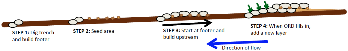
- Select the site for the ORD placement, and dig a footer trench. Into this set stones that are even with the native height of the water course bottom. These will serve as the splash apron for the ORD.
- Seed the remaining footprint of the ORD with perennial grass seeds or other hairnet root plants.
- Starting building the ORD, one course at a time, beginning with the first course half on top of the splash apron.
- Over time, the ORD will create a lense of sediment just upstream of it. Another ORD can then be constructed on top of this sediment lense, in this way gradually aggrading the drainage bottom. The first ORD will become the splash apron for the second.
- ORDs are recommended anywhere a drainage has become incised and disconnected from its floodplain.

Resources for Continued Learning about One Rock Dams
- Rainwater Harvesting For Drylands & Beyond – Brad Lancaster
- Quivira Coalition / Watershed Artisans Erosion Control Field Guide
- PDF – Hand-Built Structures for Restoring Degraded Meadows in Sagebrush Rangelands

Element
Description:
Function(s):
Context-Specific Design Criteria for ELEMENT
ELEMENTs are generally a good fit for a specific context when:
ELEMENTs may not be a good fit for a specific context when:
General Design & Installation Considerations for ELEMENTs
Resources for Continued Learning about ELEMENTs
Explore the rest of the Regenerative Waterscaping Series